Our expertise along the entire value chain
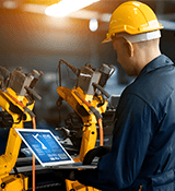
Automation & Digital Plants
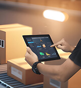
Lifecycle Services
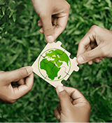
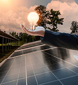
ECO Solutions
Technology Packages
Integrated Plants & Solutions
Green Steel
29.05.2024
Baosteel Orders Remarkably Powerful Bow-Type Caster to Produce the World’s Largest Slab Sections
03. - 07.06.2024
06. - 07.06.2024
17. - 19.06.2024
18. - 19.06.2024
25. - 27.06.2024
We use cookies to enhance your experience. By accepting, you agree to our cookie policy.
This is a wider card with supporting text below as a natural lead-in to additional content.